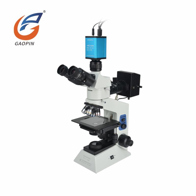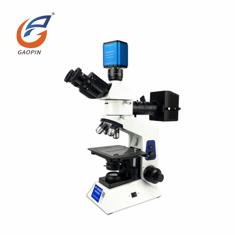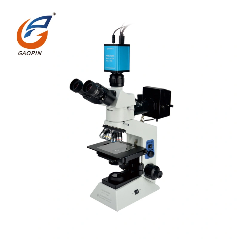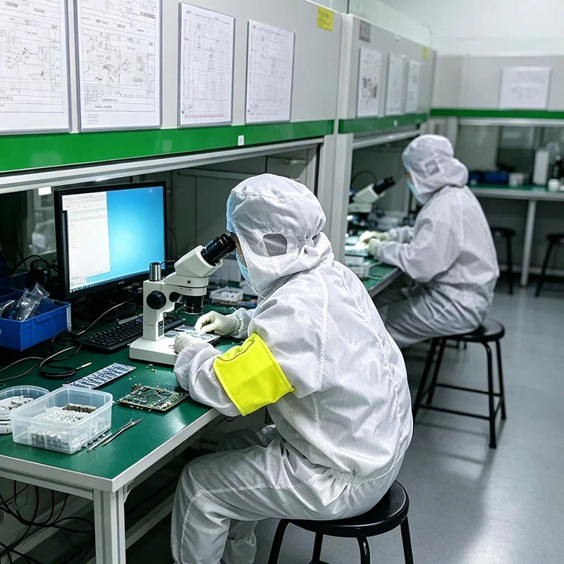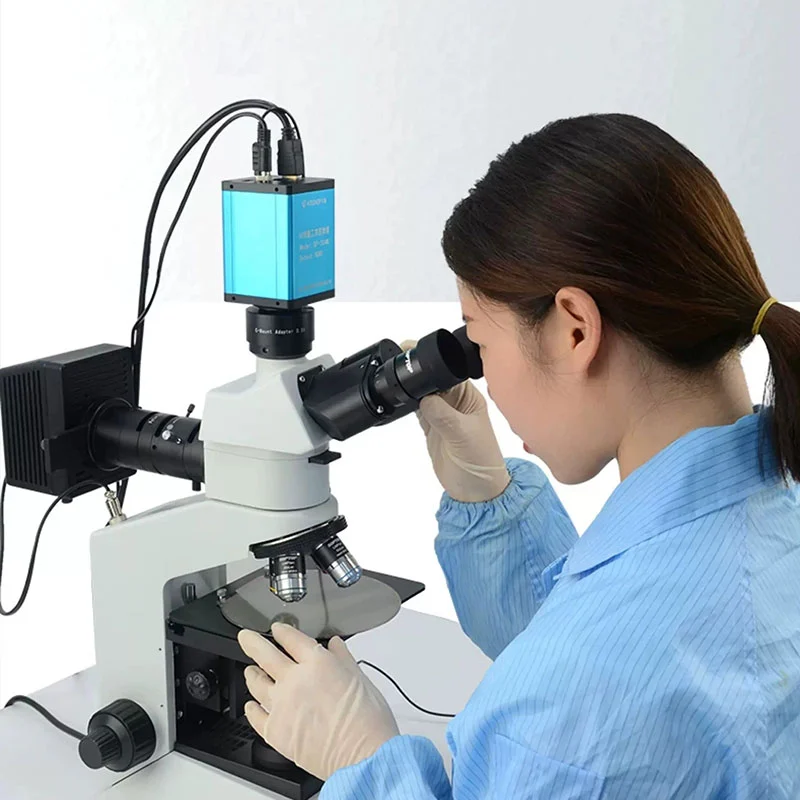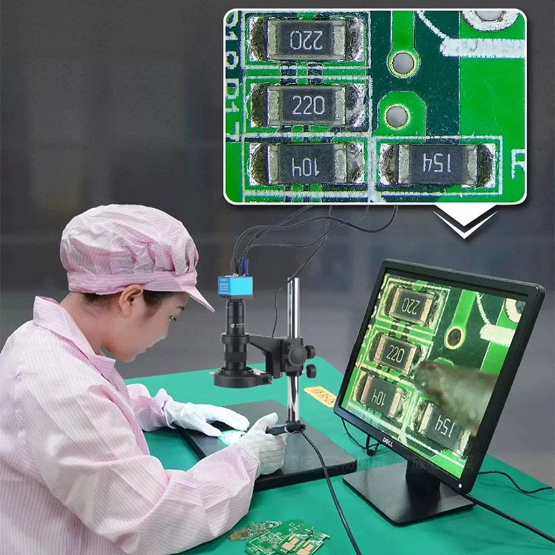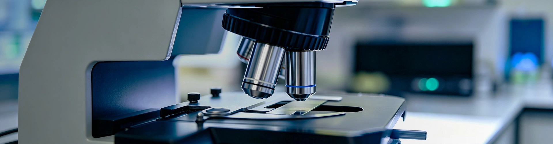
The Gaopin Upright Metallurgical Microscope is designed for reflected-light examination of opaque materials, including polished metal specimens, coatings, electronic components, and selected semiconductor surfaces. Its objectives are positioned above the specimen, making the upright configuration suitable for prepared samples mounted on a stage. Depending on the optical configuration, the microscope can support brightfield observation and optional contrast techniques for examining microstructure, surface defects, inclusions, and coating features.
Equipment selection should begin with the specimen type, preparation method, required magnification, objective working distance, and intended analysis. A microscope used for routine metallographic inspection may require a different objective set, illumination system, stage, and imaging configuration from one intended for semiconductor surface inspection or quantitative image analysis. Confirm the specifications of the proposed model before purchase.
Upright metallurgical microscopes use reflected illumination to examine light returned from an opaque specimen. Unlike transmitted-light microscopes designed for many transparent samples, they are suited to surfaces that cannot be viewed through transmitted light. Image quality depends on specimen preparation, objective numerical aperture, illumination uniformity, focus, and the optical characteristics of the material.
Optical observation alone does not identify every material phase or establish a component's compliance with a material specification. Grain-size rating, inclusion classification, coating measurement, and other quantitative analyses require appropriate preparation, calibrated image scales, defined evaluation procedures, and suitable analysis methods.
An upright metallurgical microscope places the objective above the specimen and directs illumination onto the surface through a reflected-light optical arrangement. Infinity-corrected optical systems are available in many industrial microscope designs, but objective compatibility, tube-lens requirements, and accessory specifications must be confirmed for the selected model.
The illumination arrangement affects how surface features appear. Brightfield is commonly used for general reflected-light examination. Darkfield can help reveal selected surface irregularities, scratches, or edge features by changing the illumination geometry. Polarization can improve contrast for certain anisotropic or optically responsive materials. Differential interference contrast (DIC), where supported, can emphasize subtle surface-height variations and boundaries.
These methods are not interchangeable, and optional modules are not necessarily compatible with every microscope body or objective. The best configuration depends on the specimen's reflectivity, surface finish, preparation, and the features that need to be distinguished.
Gaopin Upright Metallurgical Microscope models can be specified with different observation, imaging, illumination, and stage arrangements. The availability of each option should be confirmed for the model under consideration.
| Configuration | Primary Purpose | What to Verify |
|---|---|---|
| Binocular Upright Metallurgical Microscope | Direct observation through eyepieces | Objective range, eyepiece specifications, illumination, and stage travel. |
| Trinocular Upright Metallurgical Microscope | Eyepiece observation with an additional camera port | Camera adapter compatibility, light distribution, and supported imaging setup. |
| Brightfield and Darkfield Configuration | Reflected-light examination using different contrast methods | Objective compatibility, illumination controls, and supported optical modules. |
| Polarizing Metallurgical Microscope | Observation of specimens for which polarized illumination improves contrast | Polarizer and analyzer arrangement, rotation capability, and specimen suitability. |
| DIC-Equipped Configuration | Contrast enhancement for selected surface features | Compatibility of the DIC components with the objective and optical system. |
| Motorized-Stage Configuration | Controlled specimen positioning for repeatable inspection or imaging | Stage travel, positioning resolution, controller, software, and load capacity. |
| Wide-Field Research Configuration | Observation across a larger field of view where supported by the optics | Field number, objective coverage, image flatness, and camera sensor compatibility. |
Objective selection determines much of the microscope's resolution, working distance, field of view, and usable magnification. Higher magnification is not automatically better: it reduces the field of view and may make it more difficult to locate a feature or examine a larger area efficiently. Numerical aperture, optical correction, illumination, and specimen preparation are also important when selecting an objective.
Metallographic specimens commonly require sectioning, mounting where appropriate, grinding, polishing, and sometimes etching before examination. The preparation method depends on the material and the structure being investigated. Scratches, pull-outs, contamination, uneven polishing, and unsuitable etching can introduce artifacts that may be mistaken for material defects.
The upright arrangement is generally practical for prepared specimens placed on a stage. Tall, heavy, or irregular workpieces may exceed the available objective working distance or stage clearance. For such samples, evaluate an inverted metallurgical microscope or another inspection arrangement before committing to the upright design.
A trinocular Gaopin Upright Metallurgical Microscope can be configured with a compatible C-mount camera for digital image acquisition. Depending on the camera and system setup, the imaging workflow may support live viewing, still-image capture, video recording, and software-assisted analysis. HDMI and USB are camera-dependent output options rather than guaranteed features of the microscope's optical body.
Quantitative image analysis requires more than connecting a camera. The imaging scale must be calibrated for the selected objective and camera configuration, and the analysis procedure must suit the relevant material or test method. Grain-size statistics and inclusion analysis also depend on specimen preparation, image quality, thresholding or classification settings, and the applicable evaluation standard.
For formal dimensional inspection or metrological work, verify measurement accuracy, uncertainty, calibration traceability, and the applicable procedure. A camera and software package do not, by themselves, make a microscope a certified measuring instrument.
| Selection Factor | Upright Metallurgical Microscope | Inverted Metallurgical Microscope |
|---|---|---|
| Objective position | Above the specimen | Below the specimen stage |
| Typical specimen setup | Prepared samples placed on the stage | Suitable flat surfaces positioned over the objective beneath the stage |
| Common application | Routine metallographic examination of mounted or prepared specimens | Inspection of selected larger or heavier workpieces that can be positioned securely on the stage |
| Main consideration | Objective clearance and specimen height | Workpiece support, surface orientation, and access to the area being examined |
Neither arrangement is universally superior. The choice depends on the workpiece dimensions, surface location, preparation requirements, objective working distance, and the way the specimen can be supported. Optical performance should be compared using the actual objective and illumination configuration rather than the upright or inverted designation alone.
Different microscope types address different inspection tasks. Selecting equipment by the required result helps avoid paying for functions that are not needed or expecting an optical system to perform outside its intended range.
| Equipment Type | Typical Task | Important Limitation |
|---|---|---|
| Upright Metallurgical Microscope | Reflected-light examination of prepared opaque specimens and material microstructures | Specimen preparation and optical resolution limit the features that can be identified. |
| Stereo Microscope | Three-dimensional visual inspection of intact parts and manual assembly | Generally not intended for detailed metallographic microstructure analysis. |
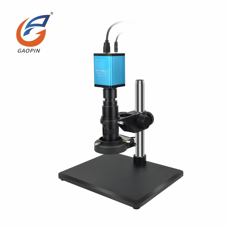
| HDMI Digital Microscope | Screen-based inspection, image sharing, and digital documentation | Capabilities depend on the imaging system; a standard single-camera view does not provide native stereo eyepiece observation. |
| Measuring Microscope or Vision Measurement System | Calibrated dimensional inspection and tolerance evaluation | Must be specified and validated for the required range, accuracy, and measurement uncertainty. |
| Electron Microscope | Imaging features beyond the practical resolution of conventional optical microscopy | Requires different operating conditions, specimen preparation, and investment. |
Conventional optical metallurgical microscopes cannot resolve every nanoscale feature. If the target structures are below the resolution limit of the selected optical system, electron microscopy or another specialized analytical technique may be required.
The complete inspection system may include objectives, eyepieces, reflected-light illuminators, optical contrast modules, a mechanical or motorized stage, a camera, and image analysis software. Gaopin can discuss available accessory combinations according to the selected model and application.
Before ordering a complete workstation, confirm mechanical mounting, objective and module compatibility, camera sensor coverage, software support, stage travel, and the required electrical connections. If the system will be used for standardized material testing, identify the applicable test method and required documentation before finalizing the configuration.
Gaopin's upright metallurgical microscope production process may include optical component assembly, reflected-light path alignment, stage and housing assembly, camera-port verification where applicable, and final product inspection. Depending on the model, relevant checks may cover image clarity, field illumination, focus behavior, objective compatibility, stage movement, and operation of the selected brightfield or darkfield configuration.
For projects with defined performance requirements, buyers should request model-specific specifications and the available inspection records. If parfocal performance, illumination uniformity, or optical resolution is important to the application, confirm the evaluation method and acceptance criteria rather than relying on general descriptions such as “high resolution” or “stable imaging.”
Test reports should identify the equipment or configuration evaluated and the parameters tested. Optical inspection records, aging tests, dimensional checks, and compliance documents serve different purposes; one should not be used as a substitute for another.
Applicable compliance requirements depend on the destination market and the components supplied with the microscope. If CE or FCC documentation is required, request the relevant declarations or reports and verify which model, electrical assembly, or accessory they cover. The exact scope may differ between a microscope body, illuminator, power supply, camera, and complete workstation.
ISO 9001 concerns a quality management system; it does not independently establish the optical performance of a particular microscope. Buyers should check the certificate's scope and validity and request product specifications and relevant inspection records for the actual order. Do not assume that every model or optional module carries the same compliance status.
Unbranded stock samples of selected Gaopin Upright Metallurgical Microscope models may be available for preliminary evaluation, subject to stock and configuration. A sample trial can help confirm specimen compatibility, objective working distance, illumination performance, image quality, and camera integration before a larger order is placed.
For selected structural or functional modifications, the estimated sample development period is 7–12 working days. Mass production is estimated at 15–25 working days after sample approval. Actual timing depends on order quantity, component availability, and the complexity of the requested changes. Confirm the final schedule and the scope of customization in the quotation or order confirmation.
For a more accurate quotation, provide:
A binocular model is primarily intended for eyepiece observation and does not necessarily include a digital output. A compatible trinocular model can accept an industrial camera through the appropriate adapter. Whether the system supports HDMI, USB, or simultaneous eyepiece and screen viewing depends on the camera and the microscope's optical design.
These tasks may be supported by a suitable camera, calibrated image scale, compatible analysis software, and an appropriate specimen preparation and evaluation method. Coating thickness measurement often requires examination of a prepared cross-section or another validated measurement technique. Grain-size and inclusion analysis depend on the relevant material standard and evaluation procedure. Confirm the intended analysis method before selecting the system.
Some configurations support optional contrast modules, but compatibility depends on the microscope body, objectives, illuminator, and optical path. Confirm the model and intended specimen before ordering an upgrade. These methods can improve the visibility of selected features, but they do not guarantee that every defect will become visible.
Remove loose particles with a clean air blower before cleaning the lens surface. If necessary, use optical lens tissue and a cleaning solution approved for the coating, following the manufacturer's instructions. Avoid paper towels, ordinary cloth, excessive liquid, and direct pressure on the lens. Do not dismantle internal optical assemblies; internal cleaning and alignment should be handled by qualified service personnel.
It can inspect accessible surfaces when the workpiece fits the stage and the objective provides sufficient working distance. However, detailed microstructure analysis commonly requires suitable specimen preparation. Large, tall, or heavy parts may be unsuitable for the available stage and objective clearance; consider an inverted microscope or another inspection method where appropriate.
The estimated sample development period for selected modifications is 7–12 working days, followed by an estimated 15–25 working days for mass production after sample approval. These are planning estimates rather than guaranteed delivery dates. Confirm the agreed schedule, sample approval procedure, and modification scope in writing.
Check the optical system, objective range, working distance, illumination method, specimen dimensions, stage movement, camera compatibility, analysis software, and available documentation. For quantitative material analysis, also confirm specimen preparation, the evaluation standard, calibration requirements, and the evidence needed to support the reported result.