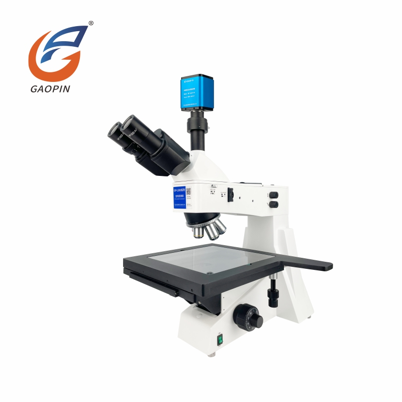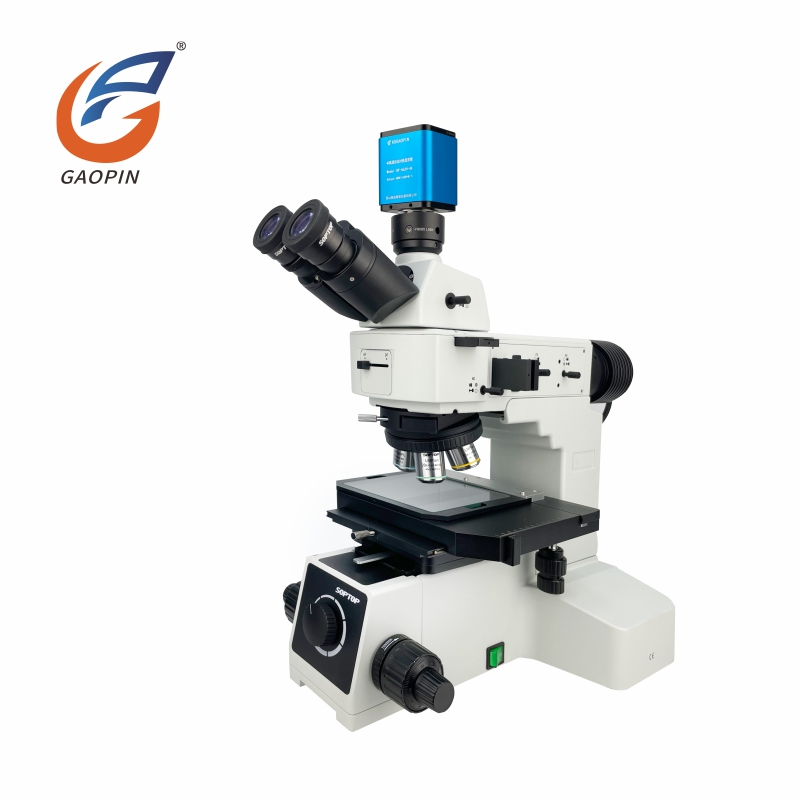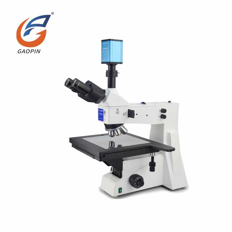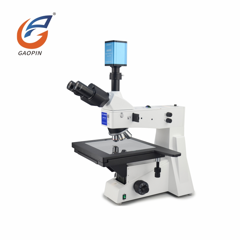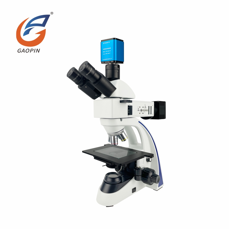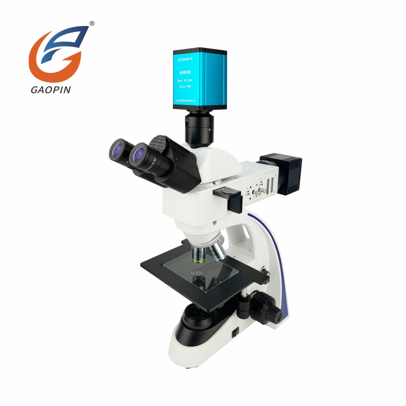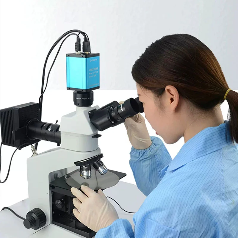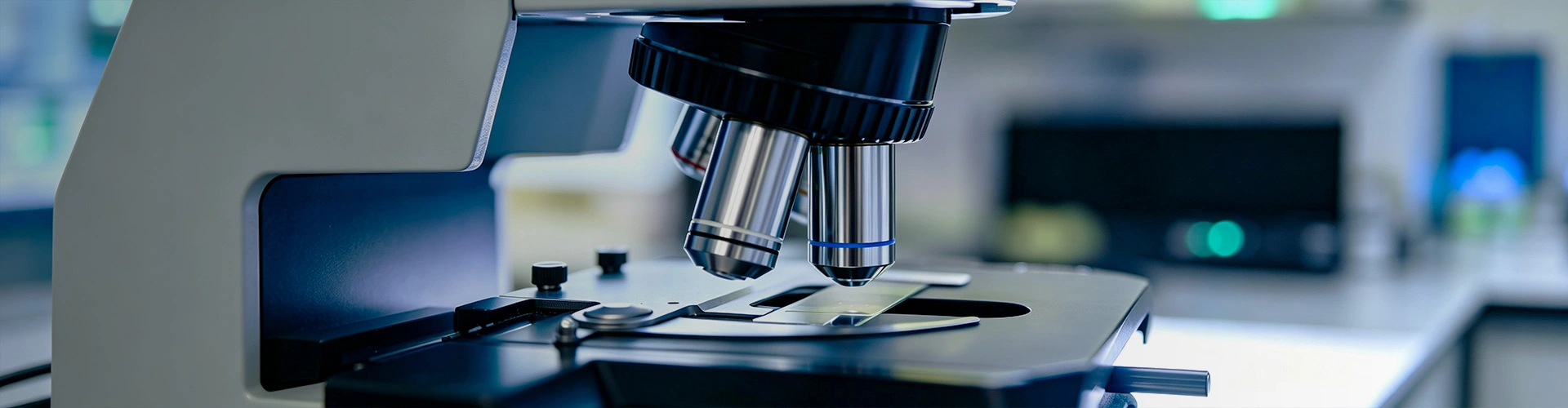
Gaopin Metallurgical Microscopes are designed for examining opaque materials under reflected-light illumination, including prepared metal samples, coatings, semiconductor materials, and precision-engineered components. Typical inspection tasks include observing grain boundaries, phase distribution, inclusions, microcracks, and other visible features in a material's microstructure.
Unlike microscopes intended primarily for three-dimensional surface handling, Gaopin metallurgical microscopes are configured for detailed optical examination of samples that do not transmit sufficient light for conventional transmitted-light observation. The appropriate setup depends on sample preparation, objective magnification, reflected-light illumination, working distance, and whether the application requires visual inspection or documented image analysis.
Available optical specifications, camera interfaces, and accessories vary by model. Buyers should confirm the technical specifications and intended functions of the selected Gaopin microscope before ordering.
Metallurgical microscopy is used to examine prepared materials and identify visible structural features. Results depend on the material, sample preparation, optical configuration, illumination, and inspection method. A microscope can support visual assessment and image documentation, but some material evaluations require complementary testing or a defined analysis procedure.
Prepared metal sections can be examined for grain boundaries, phase distribution, inclusions, and other visible microstructural features. Depending on the material and inspection objective, etching may be necessary to reveal structural details. Grain-size evaluation and other quantitative analyses require a suitable preparation method and an appropriate evaluation procedure.
Reflected-light observation can help identify visible coating defects, pores, scratches, cracks, and variations in surface structure. Cross-sectional samples may be used to examine coating layers. Quantitative coating-thickness measurement requires a suitable sample section, a calibrated image scale, and an appropriate measurement method. Total magnification alone does not establish measurement accuracy.
Gaopin metallurgical microscope configurations may be suitable for inspecting selected semiconductor surfaces, wafer features, deposited layers, and electronic material samples. The required optical resolution, illumination geometry, stage travel, and image-recording capability depend on the inspection target. Applications involving features below the resolving capability of optical microscopy may require additional instruments or analytical techniques.
Microscopic examination of prepared cross-sections and suitable component surfaces can help reveal visible cracks, inclusions, voids, and other discontinuities. A microscope can document visual evidence, but it does not independently determine chemical composition, mechanical properties, or the root cause of a material failure. These conclusions may require complementary testing and engineering analysis.
Gaopin Metallurgical Microscopes use configurations intended for reflected-light examination of opaque or insufficiently transparent samples. An infinity-corrected optical system may be available on compatible models. The optical design, objective specifications, illumination arrangement, and supported accessories should be checked against the selected model.
Objective selection affects resolution, field of view, working distance, and the level of detail visible in an image. Total magnification is determined by the objective and eyepiece combination, or by the applicable optical and imaging configuration. A higher magnification figure does not necessarily provide more useful detail if optical resolution, sample preparation, or illumination is insufficient.
Before selecting a Gaopin microscope, confirm the available objective magnifications, eyepiece specifications, total magnification range, field of view, and working distance. These parameters should be evaluated together against the smallest feature that needs to be observed.
Bright-field reflected illumination is commonly used for general observation of prepared opaque samples. Dark-field illumination may improve the visibility of selected edges, scratches, particles, or surface features by changing how light reaches the objective. Its effectiveness depends on the sample geometry, surface characteristics, and compatible optical hardware.
Bright-field and dark-field capabilities should be confirmed for the selected configuration. The presence of one illumination mode does not automatically mean that the other is included.
Polarizing components can assist in examining materials or features that produce useful polarization-related contrast. Differential interference contrast (DIC), where supported by the optical system, can enhance contrast in selected surface or material features. These techniques use different optical arrangements and are not interchangeable.
Compatibility depends on the microscope body, objectives, illumination system, and required accessories. Confirm the supported configuration before ordering a Gaopin metallurgical microscope intended for polarization or DIC observation.
Manual or motorized stages may be available for positioning samples, depending on the model. Trinocular configurations with a compatible camera adapter may support digital image capture. HDMI or USB output depends on the camera and its connection interface, not simply on whether the microscope has a trinocular head.
For digital imaging applications, confirm the camera mount, sensor specifications, output interface, software compatibility, image-recording functions, and included accessories. A camera port alone does not guarantee measurement or automated metallographic analysis.
The required observation method should be established before selecting the microscope. Binocular configurations are generally intended for direct observation through eyepieces. A compatible trinocular system can provide an additional imaging path, but software measurement and automated analysis require suitable hardware, software, calibration, and an appropriate evaluation method.
| Inspection Requirement | Configuration to Confirm | Important Consideration |
|---|---|---|
| Direct visual observation | Optical head, eyepieces, objectives, and reflected-light illumination | Results depend on optical setup, sample preparation, and operator assessment. |
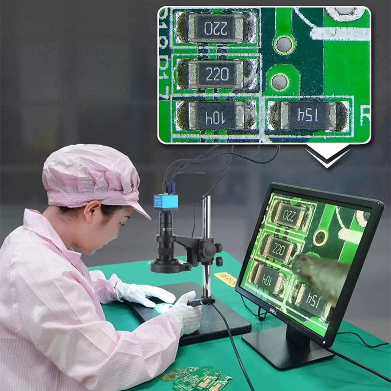
| Live images on a monitor | Compatible camera, adapter, and HDMI or USB output arrangement | Output capability depends on the selected camera and supporting hardware. |
| Length, area, or layer measurements | Camera, measurement software, calibrated image scale, and a defined measurement procedure | Accuracy must be validated for the intended measurement range and method. |
| Grain or inclusion analysis | Suitable image acquisition, analysis software, sample preparation, and a defined evaluation method | Automated results may require threshold adjustment, manual review, and method validation. |
| Special contrast observation | Compatible dark-field, polarization, or DIC components where available | Accessory compatibility and sample characteristics determine suitability. |
For purchasing teams, it is useful to define whether the system is intended for visual inspection, image documentation, dimensional measurement, or metallographic evaluation. These requirements affect the optical configuration, camera, software, calibration process, and operator training needed for the complete setup.
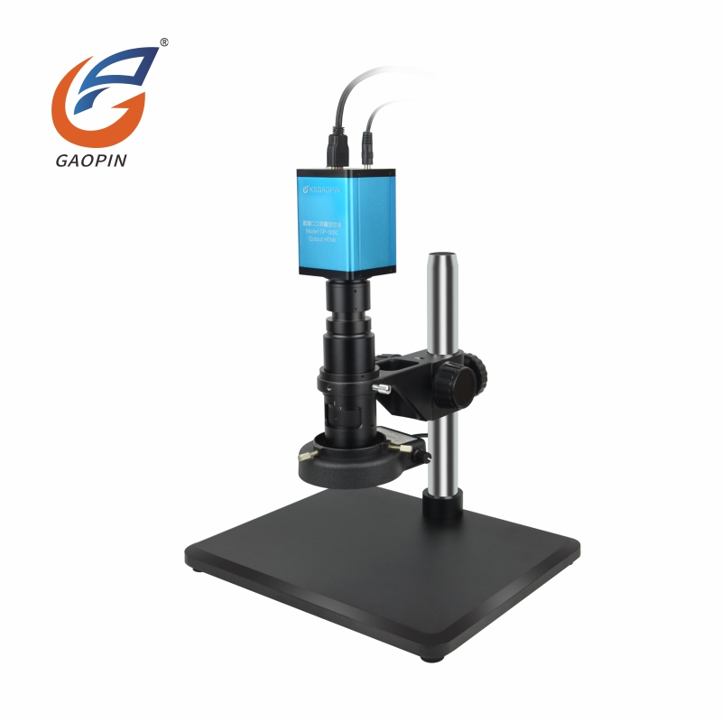
Metallurgical, stereo, and HDMI digital microscopes serve different observation requirements. The appropriate choice depends on sample geometry, the level of detail required, and the inspection workflow rather than on a single magnification figure.
| Comparison Point | Metallurgical Microscope | Stereo Microscope | HDMI Digital Microscope |
|---|---|---|---|
| Typical observation task | Prepared opaque samples and material microstructures | Three-dimensional parts, assembly, and surface inspection | Monitor-based observation and visual documentation |
| Illumination approach | Usually reflected-light illumination | Commonly incident illumination, with other options depending on the model | Depends on the digital microscope's optical and lighting design |
| Depth perception | Primarily suited to focused observation of prepared sample surfaces or sections | Stereoscopic depth perception is a principal feature | Usually presents a two-dimensional image on a display |
| Digital imaging | Available when a compatible camera and interface are provided | Available on camera-equipped or camera-compatible models | Typically designed around digital image display, depending on the model |
| Key selection concern | Optical resolution, sample preparation, reflected illumination, and analysis requirements | Working distance, depth perception, field of view, and handling space | Display interface, image capture, working distance, and required detail |
For grain structure, polished metal sections, or coating cross-sections, a Gaopin metallurgical microscope is generally the more relevant starting point. For handling small three-dimensional components during assembly or inspection, a stereo microscope may be more appropriate. An HDMI digital microscope may suit workflows that prioritize direct display output and digital documentation. Final selection should be based on a representative sample and the required inspection result.
Optical performance alone cannot compensate for inadequate sample preparation. Metallographic examination may require sectioning, mounting, grinding, polishing, and, where appropriate, etching. The preparation procedure depends on the material and the feature being examined. Scratches, pull-out, contamination, deformation, and uneven polishing can affect image interpretation or produce misleading observations.
For routine quality inspection, define the sample preparation method, inspection magnification, illumination setting, image capture conditions, and acceptance criteria. Quantitative analysis also requires an appropriate measurement scale and evaluation procedure. Consistent methods help improve repeatability between operators and inspection sessions.
When results must meet a customer specification or formal material standard, the applicable evaluation method should be identified before equipment selection. The microscope and imaging setup should then be assessed for their suitability for that method.
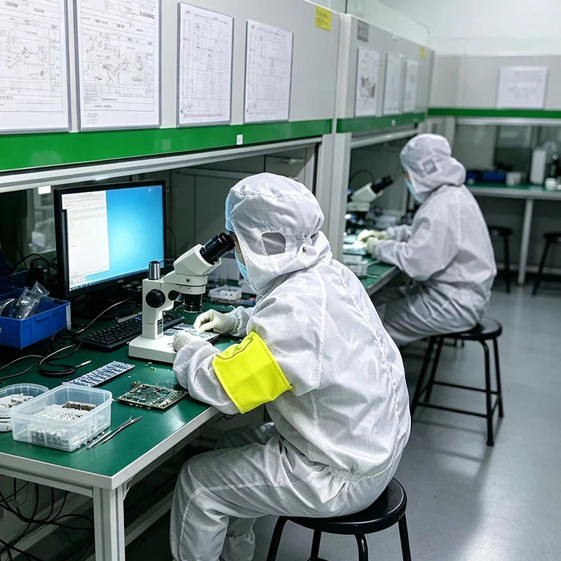
Gaopin's metallurgical microscope production involves optical component assembly, optical-path adjustment, electronic assembly, structural machining, stage installation, and finished-unit inspection. Production resources include optical adjustment benches, optical testing equipment, electronic assembly facilities, and CNC processing equipment for structural components.
Inspection procedures should be matched to the supplied model and may include optical performance checks, alignment verification, functional testing, and aging tests where applicable. The actual inspection scope depends on the product configuration and production requirements.
For procurement evaluation, buyers can request the technical specification, applicable inspection records, calibration information where relevant, and supporting documents for any required certification. Test methods, acceptance criteria, and documentation scope should be confirmed before order placement. Certification or calibration should not be assumed unless it is applicable to the specific product and supported by documentation.
Depending on the model and engineering requirements, Gaopin may provide customization of the microscope body, stage arrangement, illumination system, camera mounting, branding, or packaging. Changes to the optical path or illumination may affect compatibility and imaging performance. Proposed modifications should therefore be reviewed against the sample, working distance, field of view, and intended inspection method before production approval.
Representative sample images, cross-section photographs, or inspection criteria can help clarify the application. Where the result must meet a formal material standard or customer acceptance procedure, provide the applicable method during technical review so that equipment suitability can be assessed before an order is placed.
For projects requiring structural modifications, the indicative sample preparation period is 7–12 working days. Mass production typically takes 15–25 working days after sample approval. Actual lead time depends on the customization scope, optical and electronic components, order quantity, and component availability. The confirmed schedule should be specified in the quotation.
Logo-free stock prototypes may be available for small-batch trial orders, subject to model and stock availability. Buyers should confirm sample cost, configuration, preparation time, shipping arrangements, and whether the trial unit represents the intended production specification.
Before placing an order with Gaopin, confirm the model number, objective and eyepiece combination, illumination type, stage configuration, camera and software requirements, included accessories, sample approval procedure, packaging, payment terms, shipping arrangements, and expected dispatch date. Any required inspection records, calibration documents, or certifications should be agreed upon in writing.
A binocular microscope intended for eyepiece observation does not normally output an image to a monitor on its own. Monitor output requires a compatible camera and connection arrangement. Some trinocular models provide a camera port, but HDMI or USB output depends on the camera and supporting hardware. Confirm the complete imaging configuration before ordering.
No. Direct optical observation does not automatically include software measurement or automated metallographic analysis. These functions may require a compatible camera, suitable software, calibration, and a defined analysis method. Confirm the required functions and validation procedure for the selected model.
A suitable microscope setup can be used to observe a properly prepared coating cross-section. Quantitative thickness measurement requires an appropriate sample section, a calibrated image scale, and a suitable measurement method. The microscope alone does not guarantee measurement accuracy or replace any required standardized testing procedure.
Availability depends on the microscope configuration. Dark-field and polarization components may be offered as compatible options, while DIC requires a suitable optical arrangement. Confirm the required accessories, compatibility, and quotation scope rather than assuming these functions are included.
Typical samples include prepared metal sections, coatings, selected semiconductor materials, and other opaque samples with features that can be resolved optically. Sample preparation and illumination requirements vary with the material and inspection objective. Highly irregular three-dimensional objects may be better suited to another microscope type or inspection method.
Follow the cleaning procedure recommended by the microscope or objective manufacturer. Remove loose dust with an appropriate optical cleaning tool, and use suitable lens tissue and an approved cleaning solution only when needed. Avoid paper towels, ordinary cloths, abrasive materials, and excessive pressure. Do not apply alcohol or another solvent unless it is confirmed compatible with the lens coatings and construction.
The indicative schedule for structural modifications is 7–12 working days for sample preparation and 15–25 working days for mass production after sample approval. The actual schedule depends on customization requirements, optical and electronic components, order quantity, and component availability. Confirm the committed dates in the quotation.
Confirm the optical configuration, magnification range, working distance, illumination, stage requirements, camera interface, software functions, included accessories, lead time, and documentation scope. For measurement or metallographic analysis, also specify the intended method and accuracy requirements so the complete system can be reviewed for suitability.